N.I. Grechanyuk, P.P. Kucherenko and I.N. Grechanyuk
Keywords: electron beam technologies, melting and evaporation in vacuum, deposition of thermal barrier coatings, condensing composite materials, remelting of metals and alloys, gas turbine blades, electric contacts, specialized equipment.
Electron beam impact on the metals leading to their heating, melting and evaporation, as a new technological path in the field of material processing has been intensively developed starting from the middle of XX century [1,2].
Development of electron beam technology runs along three main paths:
- melting and evaporation in vacuum to produce materials, films, coatings; powerful (up to 1 MW and higher) electron beam units at the accelerating voltage of 20-30 kV are used; power concentration is relatively low (not more than 105 W/cm2);
- welding of metals; equipment of three classes has been developed: low-, medium- and high-voltage covering the accelerating voltage range from 20 to 150 kV; unit power is from 1 to 120 kW and higher at maximum power concentration of 105- 106 W/cm2;
- precision treatment of materials (drilling, milling, cutting); high-voltage (80-150 kV) low power (up to 1 kW) units are used, providing the specific power of 5-108 W/cm2.
Improvement of equipment [3, 4], heat sources [5], metal vapour sources [6] and development of equipment for observation, monitoring and control of the process of electron beam impact is performed simultaneously. In development of new processes for growing metal (composite) films, the main attention is given to controlling the metal vapour flows: through energy state of the condensing particles, their molecular composition, intensity, spatial distribution of the flow, etc. It is known that the widely accepted open- type evaporators, including quasi-closed ones, are characterized by instability of the directivity diagram of the vapour flow in time, even at constant temperature. Radiation load on the film growth surface from these sources is sometimes comparable to the energy of vapour flow condensation. Therefore, when they are used, it is quite difficult to produce reproducible film structures with controllable parameters. Particular difficulties arise at high evaporation rates, when microdrops are usually present in the vapour flow.
SPC «Gekont» is intensively developing the first of the above areas. Special attention is given to development and manufacturing of laboratory and production electron beam equipment for implementation of a number of new technological processes:
- deposition of thermal barrier coatings on gas turbine blades;
- producing composite materials of dispersion- strengthened, microlaminate and microporous type from the vapour phase;
- producing pure refractory metals, special alloys, ferroalloys, polycrystalline silicon for the needs of aerospace and power engineering, and aircraft construction;
- producing complex-alloyed powders of metallic and ceramic types for plasma deposition of coatings.
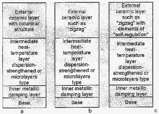
Protective coatings on gas turbine blades and equipment for their deposition. At SPC «Gekont» protective coatings on gas turbine blades are produced by electron beam evaporation of MeCrAlY (where Me isNi, Co, Fe), MeCrAlYHfSiZr alloys and ZrQrbased ceramics stabilized by Y2O3. Alongside the traditional single-layer metallic materials of MeCrAlY, MeCrAlYHfSiZr type and two-layer metal/ceramic materials, three variants of three-layer thermal barrier coatings have been developed, the schematics of which are given in Figure 1.
The simplest coating is a three-layer coating with an inner metallic (damping) MeCrAlY, MeCrAlYHfSiZr (where Me is Ni, Co, Fe or alloys on their base), intermediate composite MeCrAlY, MeCrAl-YHfSiZr-MeO (where MeO is Al203, Zr02-Y203), dispersion-strengthened or microlaminate type and outer ZrO2-Y2O3 ceramic layers (Figure 1,a) [7]. The second variant is similar to the first one with the only difference that the outer ceramic layer is made in the form of a zigzag (Figure 1, c). The most interesting is the third variant of the coating, where dispersed particle of refractory borides are added to the outer ceramic layer (ZrO2-Y2O3), which is also made in the form of a zigzag. In operation of products with such a coating, when the outer ceramic layer develops cracks, the boride particles, while oxidizing, form the respective oxides, which heal the developing microcracks. Thus, such a coating has the effect of «self-healing» or «self-restoration».
|
| Figure 1. Schematics of thermal-barrier coatings |
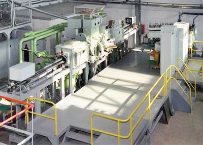
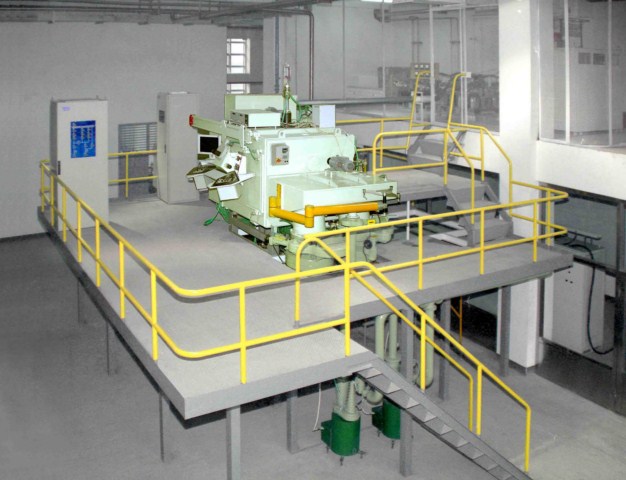
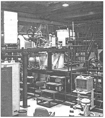
Two types of production electron beam equipment were developed for implementation of the technological processes of thermal barrier coating deposition on turbine blades [3, 4, 7-10]. Figure 2 shows the general view of a production electron beam unit L-1, which is successfully operated in the science-engineering complex «Zorya-Mashproekt», Nikolaev, Ukraine. When the unit design was developed, a traditional three-chamber schematic of equipment layout was used [7,9]. The unit working chamber is used for coating deposition proper, and the two auxiliary chambers — for loading-unloading of cassettes with blades. The unit is fitted with eight electron guns of 60 kW power each, of «Gekont» design [7], Four guns are designed for evaporation of initial materials of 70 mm diameter arranged in a row, the other four guns — for heating the coated items from below or from the top. Maximum overall dimensions of the coated items are as follows: up to 700 mm length, up to 350 mm diameter.
A feature by which the unit differs from those developed earlier [1] is the possibility of conducting not only the technological process of deposition of all the types of thermal barrier coatings, but also obtaining composition materials of the dispersion-strength- ened, microlaminate and microporous types in the form of sheet blanks of up to 800 mm diameter and up to 5 mm thickness. The above equipment can be also used for deposition of superhard wear-resistant coatings on the dies, moulds, special optical coatings (for instance, mirrors from silicon carbide), etc.
|
| Figure 2. Electron beam unit L-1 |
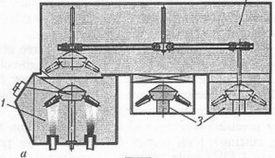
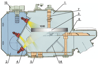
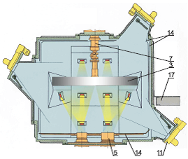
At present SPC «Gekont» developed design documentation on fundamentally new electron beam equipment for deposition of protective coatings [3, 4], The machine (Figure 3) is a vacuum unit consisting of four vacuum chambers (Figure 3, a) connected to each other: main process chamber proper /, transition chamber 2 and two load chambers (fore chambers) 3. Mounted inside process chamber / (Figure 3, b) are water-cooled crucibles 4, which accommodate ingots 5,6 of evaporation materials. Beams of electron guns 2 evaporate the ingot material, which is condensed on items 3 in the form of vapour. The quantity of the used crucibles can vary, depending on the required composition and design (two-, three-layer, microlami- nate) coating. The unit design is fundamentally new [3, 4], This unit enables deposition of all types of protective coatings, including new types of silicide coatings of microlaminate type.
|
| Figure 3. Unit for protective coating deposition |
|
| Figure 4. Fine structure of (Cu-Zr-Y)/Mo microlaminate materials |
It should be noted that the Company implemented a closed cycle of coating deposition on turbine blades, including melting of all types of ingots on nickel, cobalt and iron bases in keeping with TU U 27.4- 20113410-002-2003, and using ceramic ingots according to TU U 13.2-20113410-004-2003. Production of Ni(Co)CrAlYSi powders of 40-100 nm fraction for plasma deposition of coatings has also been mastered.
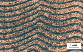
Composite materials for electric contacts and equipment for their production. Despite the wide application of the processes of evaporation and condensation for deposition of protective coatings, the unique capabilities of the zonal method for producing fundamentally new materials of dispersion-strength- ened, microlaminate and microporous types, functionally-graded materials, etc., did not find application. Development of scientific principles of producing microlaminate materials with less than 0.5 micron thickness of alternating layers at deposition temperatures higher than 0.3 of the melting temperature of the most low- melting of the evaporation materials, is a substantial scientific achievement [11]. It is known that until recently such materials were produced by the method of electron beam evaporation and subsequent condensation of metals and non-metals in vacuum at substrate temperature not higher than 300 °C [12], These data were the basis for development for the first time in the world practice of a production electron beam technology of producing thick (up to 5 mm) microlaminate materials (Cu-Zr-Y)/Mo (Figure 4) for electric contacts [13], Condensed materials Cu-(0.08-0.2) % Zr- (0.08-0.2) % Y-(8-12) % Mo are produced in a production electron beam unit L-5 (Figure 5). Technological schematic of producing this material is shown in Figure 6. Condensed materials (Cu-Zr-Y)/Mo are sheets of 1000 mm diameter and up to 5 mm thickness, which are cut up into blanks and soldered onto the contact-holder. Tensile strength and proof stress, depending on the technological condition of production can vary between 645 and 1200 MPa and from 596 to 1000 MPa, respectively, relative elongation — from 2.0 to 8.7 % [14], New composites, which were named dispersion-strengthened materials for electric contacts» (DSMC), are certified and are produced in keeping with the technical conditions [15].
|
| Figure 5. Electron beam unit L-5 |
The main advantages of DSMC materials are as follows:
- absence of silver in their composition, so that they are 1.8-3 times less expensive compared to powder electric contact materials and in terms of operating reliability are 1.5-3 times superior to the existing electrical engineering materials;
- they do not maintain arcing;
- completely replace beryllium bronze;
- can stand switching current of up to 1000 A.
|
| Figure 6. Technological schematic of producing microlaminate materials (Cu-Zr-Y)/Mo |
|
| Figure 7. Appearance of a range of electric contacts |
The most effective areas of DSMC application are as follows:
- city and long-distance electric transport (contacts used in trams, trolleybuses, trains, metro);
- lift services (passenger and freight lifts);
- port, ship cranes and other hoisting mechanisms;
- electric trolleys of all types;
- mining equipment;
- production and household electrical engineering devices, containing relays, starters, contactors, knife switches, etc.;
- tips for plasma cutting of metals and alloys;
- electrodes of resistance welding machines.
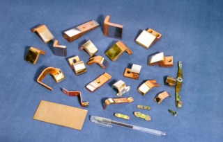
So far according to [16], more than 1.5 mln electric contacts of 370 names have been produced (Figure 7) which are successfully operating in CIS countries, Czechia and Roumania.
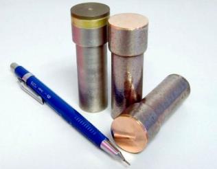
Simultaneously with introduction of materials for interrupting electric contacts into industry, the company in co-operation with Institute for Materials Science Problems, of NASU, «Generator» Plant (Kiev), Wroclaw Polytechnic Institute (Poland) is working to develop composite materials based on copper, chromium, tungsten, carbon, applied in production of slide contacts, contacts for vacuum blowout chambers (Figure 8).
Production technologies of electron beam remelting of metals and alloys and equipment for their implementation. The Company has mastered the industrial technology of electron beam remelting of wastes of high-speed steels and producing finished ingots for subsequent manufacturing of tools from them [17, 18]. The used equipment allows remelting in vacuum the wastes of high-speed steel (used tools, tool production wastes) and producing cylindrical ingots of 60 to 130 mm diameter and ingots of 140-160 mm cross-section and up to 2000 mm length.
|
| Figure 8. Appearance of contacts for vacuum blowout chambers |
|
| Figure 9. Specialized electron beam unit for melting metals and alloys |
Technological and cost advantages are as follows:
- process of ingot remelting and forming occurs in one technological cycle without subsequent ther- momechanical treatment (forging, squeezing);
- possibility of remelting lump charge;
- rapid replacement of fixtures for producing ingots of the required dimensions;
- high quality of the produced ingots after vacuum remelting;
- cost of finished ingots is approximately 2-3 times lower than that of ingots produced by the traditional technology.
|
| Figure 10. 500 kW electron beam unit for silicon remelting producing small batches of finished ingots |
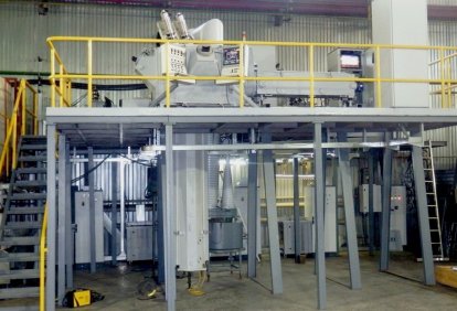
A number of specialized production electron beam units have been developed recently for melting super alloys, refractory metals, titanium and producing finished ingots of the diameter from 60 to 300 mm and up to 2500 mm length. The appearance of a unit of such a type is shown in Figure 9. New high-voltage power sources of SPC «Gekont» design and electron beam gas-discharge guns with a cold cathode developed under the guidance of V.I. Melnik were used in these units for the first time [19].
Special attention is given today to development of new technologies and equipment for melting silicon and ferroalloys. The Company supplied to Japan three electron beam units of 10, 20, 500 kW power for electron beam remelting of silicon (Figure 10).
The above examples of practical application of the processes of melting and evaporation of metals and non-metals in vacuum are a convincing proof of an ever wider application of special electrometallurgy for development of new materials and coatings.
1. Movchan, B.A., Malashenko, I.S. (1983) Vacuum-deposited heat-resistant coatings. Kiev: Naukova Dumka.
2. Zuev, I.V. (1998) Treatment of materials by concentrated energy flows. Moscow: MEI.
3. Grechanyuk, M., Kucherenko, P. Installation for electron- ray coatication of coatings. Pat. US 6,923,868 BZ. Publ. 02.08.2005.
4. Grechanyuk, N.I., Kucherenko, P.P. Installation for electron beam deposition of coatings. Pat. 2265078 RF. Publ. 12.27.2005.
5. Novikov, A.A. (2003) Gas-discharge gun and method of its control. Pat. 60377 Ukraine. Publ. 2003.
6. Zolkin, A.S. (1992) Sources of metal vapors for research and technologies. Novosibirsk: ITF.
7. Grechanyuk, N.I., Kucherenko, P.P., Osokin, V.A. et al.
State-of-the-art and prospects of development of thremal barrier coatings (TBC) for gas turbine blade units
and equipment for their deposition. Novyny Energetyky, 9, 32-37.
8. Grechanyuk, N.I., Dyatlova, E.K., Kucherenko, P.P. et al.
Electron gun with linear thermocathode for electron beam heating. Pat. 40664 Ukraine. Publ. 2001.
9. Grechanyuk, N.I., Kucherenko, P.P., Osokin, V.A. et al. (2001) Protective coating for gas turbine blades. Pat. 42052 Ukraine. Publ. 2001.
10. Grechanyuk, N.I., Osokin, V.A., Shpak, P.A. et al. (2005) Influence of technological parameters on structure of external ceramic layer in two-layer metal-ceramic coatings produced by electron beam deposition in one technological cycle. Poroshk. Metallurgiya, 3/4, 41-48.
11. Grechanyuk, N.I. Method of production of microlayer thermostable materials. Pat. 2271404 RF. Publ. 03.10.2006.
12. Iliinsky, A.I. (1986) Structure and strength of lamellar and dispersion-strengthened films. Moscow: Metallurgiya.
13. Grechanyuk, N.I., Osokin, V.A., Afanasiev, I.B. et al. Composite material for electric contacts. Pat. 34875 Ukraine. Publ. 2001.
14. Borisenko, V.A., Bukhanovsky, V.V., Grechanyuk, N.I. et al. (2005) Temperature dependences of statistical mechanical properties of microlayer composite material MDK-3. Problemy Prochnosti, 4, 113-120.
15. TU U 20113410.001-98: Dispersion-strengthened materials for electric contacts.
16. TU U 31.2-20113410-003-2002: Electric contacts on the base of dispersion-strengthened materials.
17. Shpak, P.A., Grechanyuk, V.G., Osokin, V.A. (2002) Effect of electron beam remelting on structure and properties of high-speed steel R6M5. Advances in Electrometallurgy, 3, 12-14.
18. Grechanyuk, N.I., Afanasiev, I.Yu., Shpak, P.A. et al. Method of production of blanks for tools from high-speed steel. Pat. 37658 Ukraine. Publ. 2003.
19. Melnik, V.I., Melnik, I.V., Tugay, B.A. et al. (2006) Technological equipment for electron beam refusing on the base of glow discharge electron guns. Elektrotekhnika and Elektronika, 5/6, 119-121.